Air Lubrication: The Bubble Carpet and the Compressor's Bill
Air is 800 times less dense than water, so a bubble layer under the flat of bottom, the wide underside of the hull, all but erases local friction there. The saving is real, but only after the compressors take their cut, and only at the draughts the ship actually sails.
Of all the ways a ship spends energy, dragging a steel plate through water is the one it does most. On slow, full-form ships (broad, blunt hulls such as the tankers and bulkers that carry most of the world's cargo), skin friction, the drag of water rubbing along the wetted surface, is roughly half to two-thirds of total resistance. The flat of bottom, the wide and nearly flat underside of the hull, is the largest single contributor: an enormous plate in continuous contact with the sea.
Air lubrication, part 3 of our energy-saving series, asks a disarmingly simple question: what if part of that plate touched air instead?
Eight hundred to one
Frictional drag scales with the density of the fluid touching the surface, and air is roughly 800 times less dense than water. Wherever a persistent air layer separates steel from sea, local friction all but vanishes. The hard part is the word persistent. Air wants to escape upward, the boundary layer (the thin sheath of water dragged along by the hull) wants to tear the film apart, and ship motions want to shake it loose. Every design is an answer to the same question: how do you keep the air where it works?
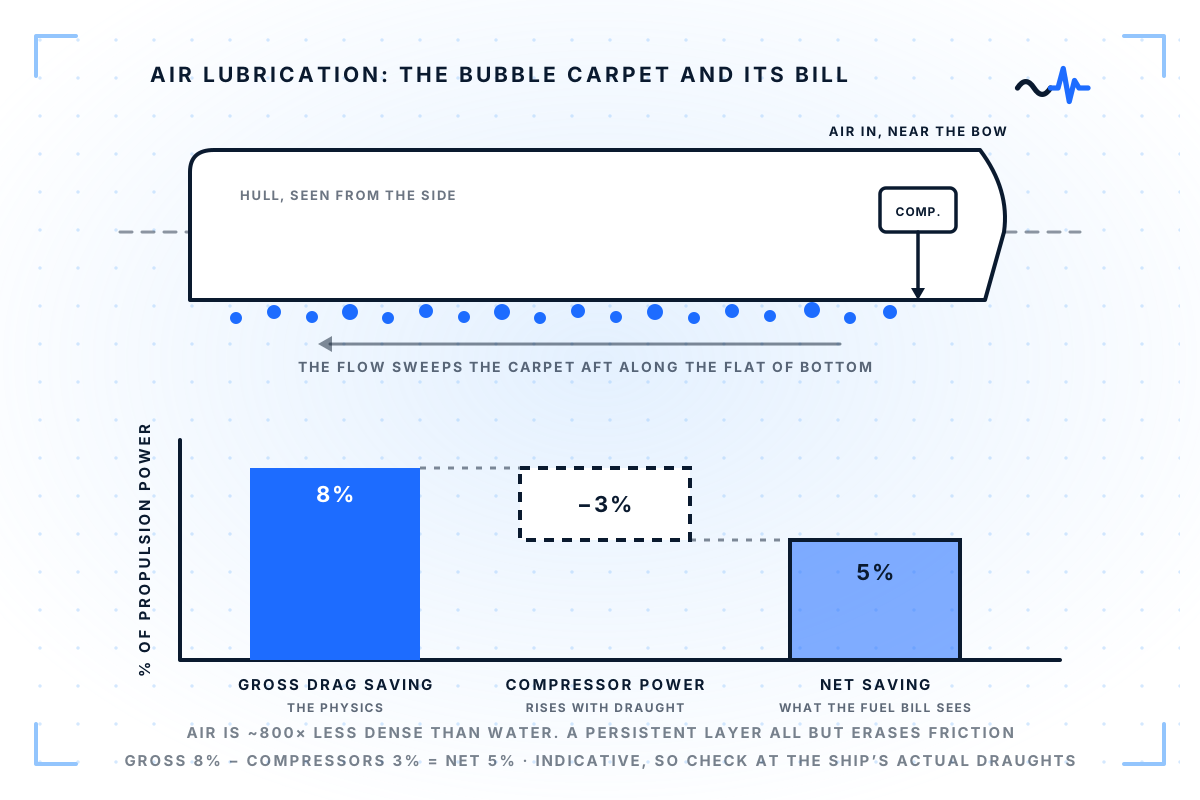
Bubble systems inject air through arrays of openings near the bow of the flat bottom, forming a carpet that the flow sweeps aft along the hull before it escapes at the sides and stern. The carpet must be continuously renewed, and that renewal sets the air demand.
Air-cavity systems go further, recessing part of the bottom so the air sits in shaped pockets as a stable film. The hull modification is more invasive, but the trapped layer lives longer and the air consumption drops.
The honest arithmetic
Air is free; compressed air is not. The compressors that feed the layer have to push the air out against the hydrostatic pressure at the bottom of the hull, which is simply the weight of the water column standing above the outlets. The deeper the draught (how far the hull sits below the waterline), the more water there is to push against, so the compressors work harder and draw more power. And they run whenever the system runs.
This is the classic net-versus-gross case from the series opener: the gross saving is what the hull gains, and the net saving is what is left once the system's own energy use is subtracted. Suppose the air layer delivers a gross resistance saving of 8%, so the hull needs 8% less push to hold its speed. The compressors that keep the layer alive absorb 3% of propulsion power, and that comes straight off the gain. What the fuel bill actually sees is the difference: a net 5%. Vendors quote the number that flatters; the ship pays the difference. An evaluation that does not check the compressor load at the ship's actual draughts, rather than the trial draught, is incomplete.
Service conditions take their own bite. Sea state disperses the layer. Operating far from the design draught changes both how the layer behaves and the back-pressure the compressors work against, the pressure standing at the outlets that they must overcome to deliver air at all. And a system down for maintenance saves nothing while its equipment still rides along. The saving is real, but it has to be managed: it is not a fixed bonus that arrives with the equipment.
Who should look at it
The benefit is largest where the flat of bottom is large and the draught moderate. Cruise ships and car carriers fit that description unusually well: they carry a beam four to five times their draught, where a laden tanker is nearer three. Most of their wetted surface is therefore flat bottom, which is the part an air layer can actually blanket. Their injectors also sit eight or nine metres down rather than twenty, so the compressors have far less water above them to push against. Injection power is set by depth, not by speed.
Their service speed then cuts both ways, and it is usually quoted only one way. In absolute terms the prize grows, because the friction bill in kilowatts climbs close to the cube of speed. But the air layer gets harder to hold. Faster flow scrubs bubbles off the hull, while the buoyancy that pins them there does not change with speed, so a fast ship needs more air to keep the same coverage. Starve the layer and it breaks into patches, and the saving collapses with it. A fast ship can certainly be air-lubricated. The compressors simply have to be sized for the speed she actually keeps, decided at the design stage rather than discovered in service.
One thing is worth stating plainly, because the industry often says it backwards: friction is not a larger share of resistance on a fast ship. As speed rises, wave-making grows quicker than friction does, so friction's share of the total falls. Slow tankers and bulkers sit at the top of that range, not cruise ships. The case for these hulls rests on their shape.
Fine-form hulls, the slender and sharply shaped ones, offer the air less area to work on. If they also sit deep in the water, the compressors cost more to run.
Fitting the system is a real project, not an add-on: hull penetrations below the waterline, air piping, a significant new electrical consumer, and controls tied into the bridge. Class societies publish dedicated guidance for exactly this scope.
The technology with a switch
One property makes air lubrication a gift to honest measurement: it has a switch. Comparative runs with air on and air off, under documented conditions, give a cleaner attribution than any fixed device can offer. It is the same trial discipline the wind article described, made easy. An owner who never runs the comparison is choosing not to know.
If your fleet had an air lubrication system today, would your monitoring setup be able to say, a year on, what it actually earned?